To conceptually design a database, you need to first collect requirements and analyze it to understand the data “needs” of the business. The first step requires a deep dive meeting with the business users. Information architect needs to ensure the business “needs” are met, so a meeting with the business users to understand how it will be used is critical.
EER and UML data are methods of formalizing data requirements. There are three basic conceptual models that you should know, which are ER, EER, and UML and they all build on each other respectively. These models are created to be user friendly and have graphical representation so that it can be easy to communicate between an architect and users who will use it. It’s also flexible enough where new requirements can be added and existing requirements can be modified. These models are implementation independent, because its only goal is to “adequately” define the data requirements. Conceptual models do have limitations, which should be noted on the document, so it can be followed up during development. Once a conceptual model has been agreed upon by the two parties, it can be mapped to a logical data model. This is a phase where database designer can think about how it will be implemented. Lastly, logical data model can be mapped to an internal data model during physical design setup.
Let’s look at entity relationship (ER) model, which is one of the most popular conceptual data model. It has three building blocks: entity, attribute, and relationship “types”. Entity “types” in a business sense is collection of entities, like a person or a product. When you build a conceptual data model, note that entity “types” are depicted using a rectangle (as shown below) and it focuses on entity types and not individual entities. For example, it focuses on “employee” and not “bob”.
Other entity types can be student, instructor, vehicle, and manufacturer. As long as the entity “types” consists of multiple entities that have similar characteristics.
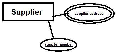
Next building block is attribute “types”, which represents a set of properties for entity “types”. For supplier, we can have supplier name, supplier address, and supplier number for example. Supplier number can be unique, which means it doesn’t “repeat”, but name for example may overlap.
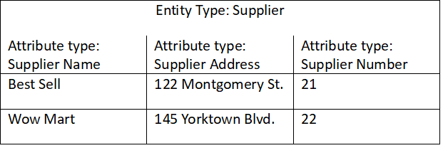
Each column in the above table below attribute types are entities with its own attributes. Attribute “types” are represented in ellipses for conceptual model like shown and are connected to the entity “types” with a line to let viewers know that it is an attribute types related to that specific entity types. A simple attribute type can’t be further divided into parts, but there are what we call composite attribute type that can be decomposed into multiple attribute types. For example, supplier address will be a composite attribute type since it can be broken down into street name, zip code, city, and country and they will all be its own attribute types.
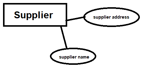
In the above ER model, we have a simple rectangle for entity type and ellipses for attribute type. However, the ellipses can have more designs. Key attribute type or “unique” attribute type can have the name underlined to represent its uniqueness for example.
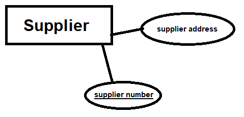
Supplier number above is underlined to represent its key attribute type. This is a unique attribute type with values that are distinct for individual entity. A great example of key attribute type is a serial number, as there will never be same serial numbers for same product number. Another great example is social security number. Key attribute type can also be a combination of multiple attribute types.
Sometimes, attribute types can be multi-valued, meaning it can have multiple values for that attribute. A single valued attribute type would be something like a social security number, since one entity can’t have more than one social security number. Multi-valued attribute type would be something like a phone number or email, since one entity can have more than one of each. When it is a multi valued attribute type, you can represent it on the ER model with double ellipses.
We also have what we call “derived attribute type”, which is an attribute type that can be derived from another attribute type and are represented using a dashed ellipse instead of a regular ellipse. For example, age can be derived from birthdate.
There are some limitations as well on ER model regarding attribute types and you can’t represent certain things. For example, you can’t represent domains. A domain is set of values that are assigned to attribute type. Gender for example can have a domain of 2, male or female.
Last building block is relationship types, which makes association between two “or” more entity types with a rhombus. For example, we have teacher and student entity types that are represented with a rectangle and a rhombus that shows the relationship between the two. We can even add “class” and “semester” entity types if we want to show more relationship connections.
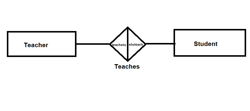
The rhombus is simple a bi-directional arrows pointing to each entity types in the above image. Teacher teaches student and student is taught by the teacher. Individual entity relationship instances are not represented in the ER model, it’s types to types.
The relationship type can have various characteristics like degree and roles, cardinalities, and relationship attribute types. Degree is simply the quantity count of entity types involved in the relationship. Unary relationship has one, binary has two, and ternary has three entity types. Teacher and student above is a binary relationship with a degree of two. Roles are simply given to entity types to depict what the entity type is doing for the other entity type in the relationship and is written within the rhombus and below it. In the above example, we have “teaches” below the rhombus and “teacheestudent and studenttaughbyteacher” within the rhombus. A unary relationship can exist for entity type “employee” for example, where it has the roles “supervises by” as well as “supervises and supervised by” within the rhombus of a single entity type.
Cardinalities is what specifies the minimum and maximum of relationship’s instances. The minimum is either 0 or 1. 0 means partial participation and it states that an entity can occur without being connected through that relationship type to another entity. If the minimum is 1, it is known as total participation, and the entity must always be connected to other entity through an instance of the relationship. Total participation is also known as existence dependency since it depends upon the existence of another. Maximum cardinality is either 1 or N, where 1 means it can only be involved in one instance of that relationship type and N means any number bigger than 1.
For binary relationships, cardinalities can be 1:1, 1:N, N:1, and M:N. Let’s go over several examples. Relationship types are characterized by maximum cardinality for roles as shown.
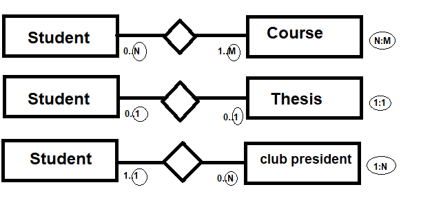
As shown above, a course entity type can have minimum of 0 student and maximum of N students. This is depicted on the “student” entity type side of the relationship relative to the rhombus. Respectively, student entity type can have minimum of 1 course and maximum of M courses. Thus resulting in N:M cardinality using the maximum cardinality for roles. Next, we have student to thesis where thesis doesn’t need a student assigned but if they do, maximum of 1 student can be assigned. While student doesn’t need to have thesis but if they do, they are allowed maximum of 1. Lastly we have student to club president where student doesn’t need to be the club president but if they decide to be one, they can do as much as they can handle. But club president role needs to be filled by minimum of 1 student and there can only be 1, so that’s the max, hence 1:N relationship.
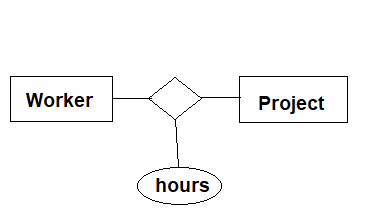
Relationship can also have attribute as shown below. Ellipse is attached to the rhombus and not to worker or project because the attribute type represents how much the worker put in for a specific project and project hour is broken down by the worker, so it can’t be a sole property of either entity types and needs to be modeled as attribute type of the relationship type.
While ER model is easy to make and is very user friendly for conceptual data modeling, it has lot of limitations. Its limitations are temporal, consistency, doesn’t support definition of functions, and domain exclusion.

You must be logged in to post a comment.